Several of the operations covered in this tutorial are:
Bring up Pro/E as discussed in previous tutorial.
To begin, create a part file named fixture
part>create>(enter fixture as filename)
To begin, we want to establish our datum planes. Do this by:
feature>create>datum>plane>default
If you want, you can also create a coordinate system as you did in the previous tutorial.
We then want to make the first protrusion, creating the first solid feature.
create>solid>protrusion>extrude | solid | done
Then indicate it will be a one-sided extrusion.
one side | done
At this time, you are required to select a sketch plane and reference plane:
choose DTM3 and OK for the sketch plane,
then bottom from the menu and finally DTM2 for the reference plane.
Notice that the yellow side of DTM2 is facing the bottom of the screen.
Create a square section profile:
sketch>rectangle
Rather than drawing four lines click using the left button opposite corners of the rectangle. For this example, place the center of the square at the origin of the datum planes.
Important: Count grid squares so that the square is centered about DTM1 and DTM2. If its not, erase it and redraw.
Now you need to constrain the square. In the previous tutorial, you aligned two edges of the initial feature to locate it. For this feature, we will locate it with center lines:
sketch>line | centerline | 2 points
Draw center lines directly on top of the edges of DTM1 and DTM2. The exact length is not important. Make sure your lines are dashed, indicating you are drawing center lines.
Now align the center lines with the datums; first clicking on the center line and then again on the datum.
With the square located, you can now size it by dimensioning the top and right edge. The left button choses the line to dimension, the middle button places the dimension.
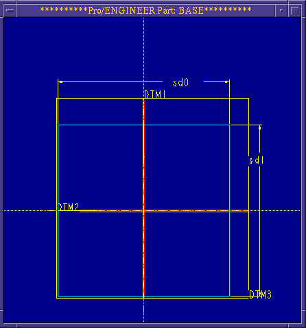
Your section profile should now look like Figure 1. You do not need additional dimensions to locate the square because Pro/E will assume syemmetry about the center lines aligned to the datum planes. In a sense, the square is anchored to the center lines which are, in turn, anchored to the datums.

Figure 1
Regenerate the section profile and modify the dimensions so the two sides are 6.25.
Regenerate a final time and choose done.
Specify a blind | done extrusion and enter a depth of 1.5.
Click OK and set the view to default.
You should have a shape resembling that shown in Figure 2.
Save the part (as you should after every successful feature operation) with dbms>save.
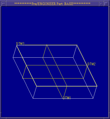
Figure 2
feature>redefine
The Changing Feature Specifications mini-tutorial will give more information on this.
Now we will use the shaft command to place a shaft on top of the block. Starting at the feature menu:
create>solid>shaft>linear | done
A second graphics screen will then appear.
Note: For this revolve operation, a half cross-sectional shape is required. Also, the orientation of the shaft should be kept in mind when drawing the cross-section. (i.e., if the shaft is to be vertical, the axis of rotation and the center line will be along one of the vertical edges of the cross-section.) This operation revolves the sketch, therefore only requiring the half cross-section.
Sketch a rectangle roughly three times high as it is wide.
sketch>rectangle
Sketch the center line along one of the vertical edges.
sketch>line>centerline>vertical
Click once on one of the vertical lines.
Dimension and regenerate your sketch.
Modify the rectangle to be 2.75 high and 1.0 wide. Regenerate again. It should look like Figure 3.
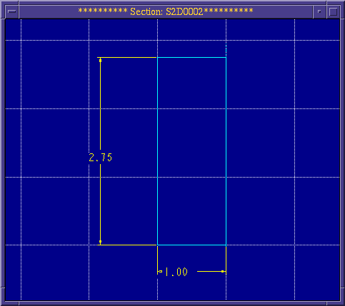
Figure 3
After finishing the sketch, you will be prompted for the placement plane. Choose DTM3.
You are then prompted for the feature's placement location on DTM3. Click in the middle of DTM3. A red directional arrow will appear. Ensure that it is pointing away from the block, and click on okay.
You will be prompted to give two edges for placement of the shaft. Click on DTM1. Type yes when prompted whether to align the feature to the reference. If the prompt asks for a distance rather than whether to align to a datum, typing in a zero (0) distance will have the same effect as aligning.
For the second edge, repeat this process for DTM2.
The shaft feature is now specified. Click on OK in the feature dialog to finish.
Your part should look like Figure 4.
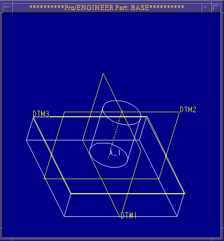
Figure 4
Then next feature that we will work on will be the holes. Notice that instead of using a datum for a placement plane, we will use a planar surface on the part. First specify the type of hole:
create>solid>hole>straight | done
Next indicate what type of location dimensions you will use:
linear | done
For the placement plane, click on the bottom of the fixture (the side closest to you) in the general location of the first hole. Examine Figure 5 for the placement of the four holes.
Choose DTM1 for the first reference and enter 0 for a distance. Choose DTM2 for the second reference and enter 1.75 for a distance.
Choose one side | done for the direction of the hole.
Choose thru all | done for the distance of the bore.
For the prompted diameter, enter 0.5
Click on OK to finish the hole feature operation. Notice that each hole is created with an axis down its center. This datum axis is labeled (e.g., A_1) just as datum plane features are.
Repeat the above operation to create a total of four holes. Make sure that you click reasonably close to the final location of the hole so Pro/E knows on which side of the datums you want to place the holes. The distance away from the center will be the same. The only difference will be in choosing which datum to align to and which to offset 1.75.
The part should now look like Figure 5.
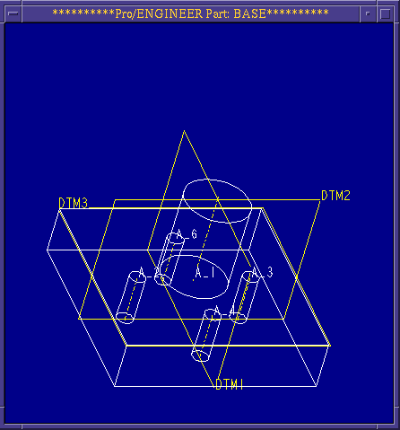
Figure 5
If the distance you typed in was wrong (unless you typed 0), you can choose modify from the part menu. Choose the hole by clicking on its axis. Constraint dimensions now appear and you can change values and regenerate just as you do in sketch mode.
If you have aligned a hole to the incorrect datum or otherwise mis-specified the hole, you can redefine it or remove it by choosing delete from the feature menu.
Now we are going to use the cut operation to cut the corners off the fixture block.
create>solid>cut>extrude | solid | done
one side | done
You are then prompted for the sketching plane, choose DTM3.
The directional arrow should be pointing into the block. If not choose flip. Now click Okay
You will be prompted for the reference plane, click on top from the menu, and then DTM2.
You can cut all four corners at one time by sketching four closed profiles, one for each corner. You can do this because all of the other specifications for all four cuts are the same.
Sketch a triangle in one of the corners of the block, with two sides of the triangle forming the corner of the block, and constrain it.
Align two of the edges of the triangle with the edges of the block.
Dimension as seen in Figure 6.
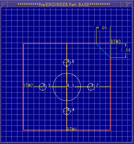
Figure 6
Since all four cuts are identical in shape and size and are symmetric about DTM1 and DTM2, you can use this to your advantage when creating and constraining the remaining triangles.
First, create horizontal and vertical centerlines on top of DTM1 and DTM2 and align them.
Next, mirror the initial triangle across DTM1.
Choose Geom Tools>Mirror.
Click on the vertical center line over DTM1 to indicate the mirror plane.
Mirror the complete triangle by choosing all | done in the mirror menu. It will now mirror across the center line.
Repeat this process, except this time use the horizonal center line and mirror both triangles to the bottom.
Regenerate the section profiles. Notice that you did not have to dimension the other triangles. Because they were mirrored across center lines, their locations, size, and orientation had been set based on the original triangle. Changes to the size of the original triangle will now alter all four.
Click on done, and orient the directional arrow to point inside the triangle. Click okay.
Indicate the cuts should go thru all and then OK.
The part should now look like Figure 7 after reorienting the view in the view menu.
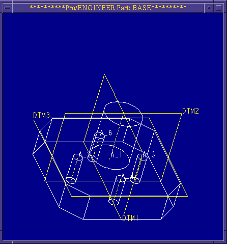
Figure 7
Now we will create a slot. Instead of starting on the outside of the part and cutting in, we will start in the middle and cut out both directions.
create>solid>slot>extrude | solid | done
Now indicate that you are going to cut both directions:
both sides | done
Choose DTM1 as your sketching plane. Click okay. The direction of the red arrow is not as important since we are cutting both directions.
For your reference plane, choose bottom, and DTM3.
The profile you are creating will look like a U centered about DTM2 and aligned to the top of the shaft. Sketch twovertical lines of equal length on both sides of DTM2 at the top of the shaft.
Align the tops of the vertical lines with the top, horizontal edge of the shaft.
Now create the arc connecting the bottom on both lines. Click on arc>tangent end. Then click on the two bottom end points of the vertical lines.
Align the center of the arc with the centerline of the shaft and the end points of the vertical lines to the top of the shaft.
Place one size dimension for the radius of the arc by clicking on the arc once and placing the dimension. Place a second size dimension by specifying the distance of the center of the arc to the top of the shaft. Click on the center of the arc and then top edge of the shaft before placing the dimension.
Regenerate the profile and modify the radius to 0.2 and the height to 0.5. Now finish up:
regenerate | done
Make sure the direction arrow points into the cut and click okay.
Since the cut is going to both sides, you have to specify the distance to cut going both directions:
thru all | done and then again: thru all | done.
Finally, OK.
The next feature operation will be a round on the top of the shaft.
create>solid>round>simple | done
Now indicate the round will be of constant radius and will be located by selecting a series of edges:
constant>edge chain>one by one
Then select the two arcs which make up the bottom of the shaft. Use Query Sel to choose the hidden arc(s).
Choose done and enter a specific radius of the round: 0.25.
Repeat the round operation for the top edge of the shaft, using the same radius.
The result should look like Figure 8.
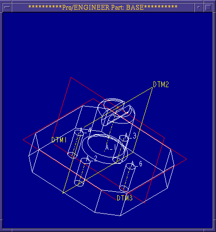
Figure 8
The last feature operation that we will do to this part is to chamfer the top of the fixture.
create>solid>chamfer>solid>edge>45 x d
Use 0.25 for the chamfer dimension. This will create a 45 degree chamfer, .25 deep.
Click on all the top edges of the fixture (8 total).
Click on done when finished.
The final picture will look like Figure 9. You can manipulate the view using the shading command found in the environment menu.
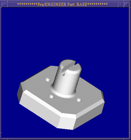
Figure 9
Pro/ENGINEER Tutorial Home Page;